In this exercise you are going to draw a very simple shape - a rectangle - in several different ways. The purpose of this is not to create a realistic CAD drawing, but to show you how to draw easily and accurately with the CAD using a variety of methods.
You will learn how to:
Use specific coordinate locations.
Undo an operation.
Use the [Home], [End], [PgUp] and [PgDn] keys.
The arrow keys.
Input polar coordinates.
Use a locked cursor.
Use geometry.
Use a grid.
Use jumps and snap modes.
Save your drawing.
Ensure your drawing screen is blank by selecting File ► New.
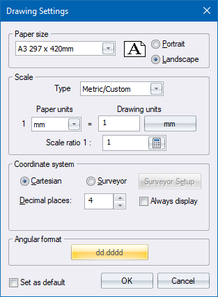
In this tutorial you begin with a blank screen representing a blank sheet:
A4 paper at a scale of 1:1.
Units will be millimetres.
Cartesian mode
Decimal angular format (dd.dddd) with angles measured anti-clockwise from 3 o’clock.
Landscape orientation.
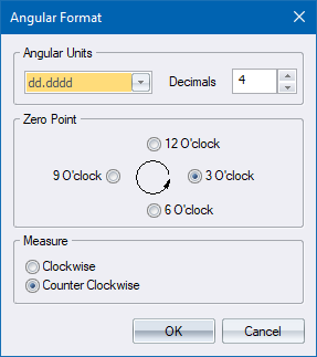
Edit the settings so they look like the example shown above, and then click OK twice (x 2) to save your changes.
 in the Zooms toolbar, or
by selecting View ► Redraw.
in the Zooms toolbar, or
by selecting View ► Redraw.You can change paper size, scale, units, etc. at any time during drawing. See Drawing Settings.
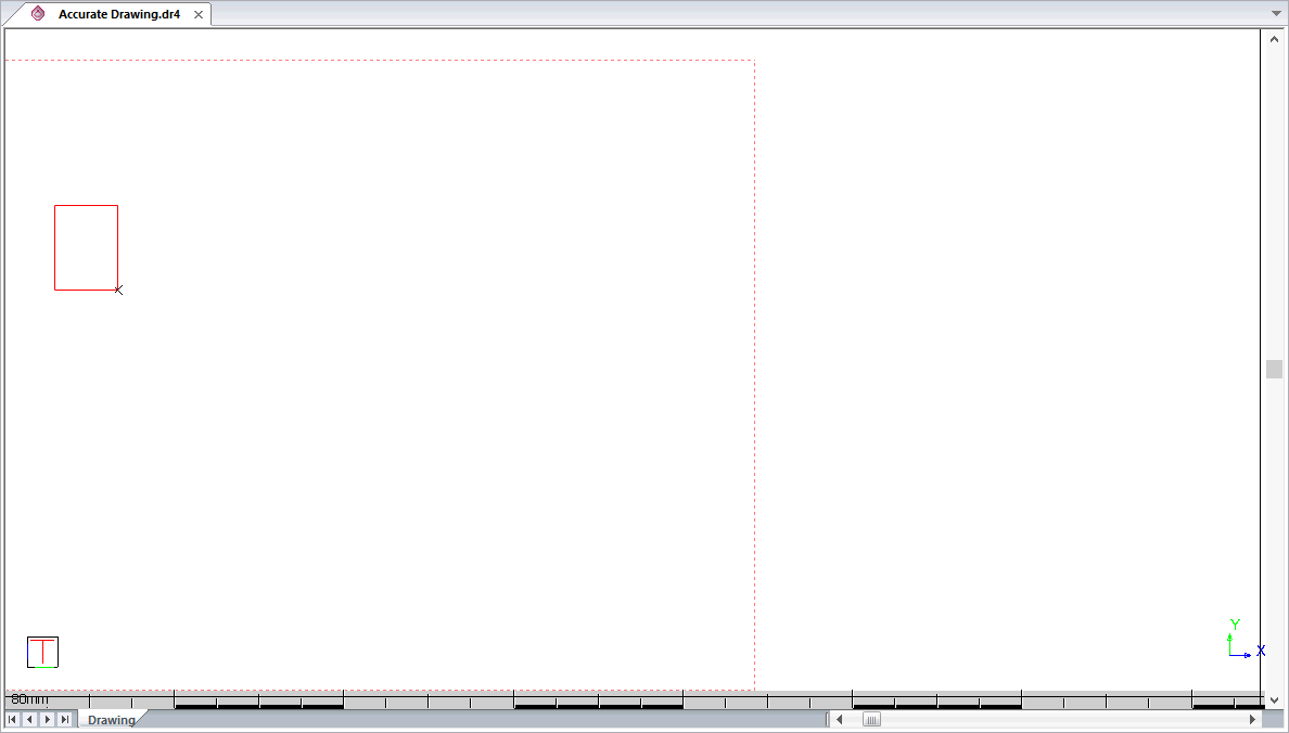
You are going to draw your first rectangle in the top left corner of the screen.
Click the Rectangle icon  or select Draw
► Rectangle.
or select Draw
► Rectangle.
You are prompted to:

You are now going to position the
first corner of the rectangle at a specific coordinate location, using
the Coordinate Jump
function. To do this, ensure that your cursor is in the Drawing
Area, and then click the Jump Coordinate icon  in the Jumps toolbar or select Tools ► Jumps
► Coordinate Jump. Alternatively, press [U].
in the Jumps toolbar or select Tools ► Jumps
► Coordinate Jump. Alternatively, press [U].
 [U] is called
an Accelerator because it is a fast way of accessing the Coordinate Jump
function.
[U] is called
an Accelerator because it is a fast way of accessing the Coordinate Jump
function.

 to accept these
coordinates.
to accept these
coordinates. 

Click the Jump Coordinate icon again to access the move
to coordinate function.
You are prompted to:


Ignore this prompt for the time being and press [Esc] or [Spacebar] to terminate the function.
You are now going to Undo the rectangle you have drawn so that if you do something wrong later in this tutorial you can Undo it and try again.
Click the Undo icon  or use the Edit menu.
The rectangle disappears. You can undo a maximum of 1000 actions in this way.
 or
using the Edit menu.
or
using the Edit menu.As you have undone the rectangle you drew, you should now have a blank drawing area.
function again.You are prompted to:
to access the Move to Coordinate function.You are prompted to:
Type “-120 80” and press [Enter] to accept these coordinates. The cursor moves to coordinate position -120 80 in the top left part of the screen.

You are now going to define the precise position of the second corner of the rectangle using the keyboard.
Accurate horizontal and vertical movement is achieved with the arrow keys.
Accurate diagonal movement is achieved with the [Home[, [PgUp], [End] and [PgDn] keys; and the Polar Jump function.
Press [PgDn}. The second corner of your rectangle is below and to the right of the first corner. If you have a numeric keypad, you will note that the [PgDn] key is the bottom right key on the keypad, corresponding to the direction in which you want to move.

Note that the
rectangle outline is not coloured and that AllyCAD is still prompting for the second rectangle corner.
This is because while you have moved the cursor to the new position, you
have not yet accepted this as the position for the rectangle corner.
To accept the position as the second rectangle corner, press [Enter] again. Alternatively you can click, however,you may accidentally move it slightly off the correct position resulting in an inaccurate rectangle.
The rectangle becomes coloured and you are prompted to:

When you use the
[Arrow], [Home], [PgUp], [End] or [PgDn] keys, you have to press [Enter] an
extra time in order to fix the cursor position after the cursor has moved.
This allows you to re-adjust the cursor position if you are not satisfied
with it. For example, you may want to shift the cursor an additional 10mm
to the right before accepting its position.
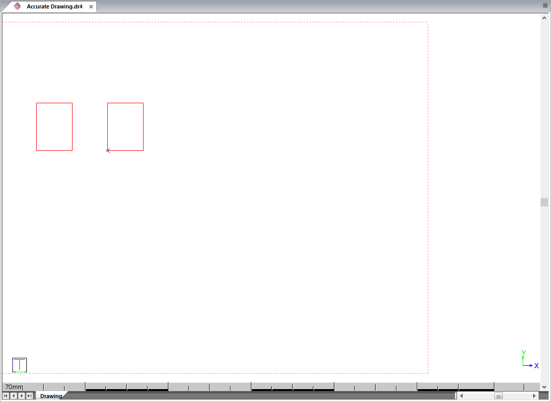
You are going to draw the next rectangle with lines. You are also going to position this rectangle relative to the first rectangle you drew using the [PgUp] and [PgDn] keys.
 .
.You are prompted to:
Indicate start position of line
Press [Right-Arrow].

The program remembers the horizontal distance that you entered when you pressed [PgDn] key, in this case “30”. Press [Enter] to accept this distance.
The cursor moves 30mm to the right. Press [Enter] to accept this position as the first point in the line of your new rectangle.
Indicate end position of line
Press [UpArrow].

The program remembers the vertical distance that you entered when you pressed [PgDn], in this case “40”. Press [Enter] to accept this distance.
A vertical line 40mm long is drawn. Press [Enter] to accept this line.
Indicate end position of line
Moving the same distance again, you now need to draw the next line in the rectangle - a 30mm horizontal line. Press [Shift+RightArrow]. You are not asked how far you want to move and the cursor automatically moves 30mm to the left, drawing a horizontal line. The program has remembered the distance you last moved horizontally. Pressing the [Shift] key at the same time as the arrow key has caused it to move this distance automatically.
Press [Enter] to accept the new horizontal line.
Press [Shift+DownArrow]. A 40mm vertical line is drawn. Press [Enter] to accept the line.
Complete the rectangle by pressing [Shift+LeftArrow]. A 30mm horizontal line is drawn. Press [Enter] to accept the last point on the rectangle.
Indicate end position of line
Ignore this prompt and click the
Rectangle icon  .
.

Move your cursor off the toolbar
and onto the Drawing Area. Click the Jump Coordinate icon  to access the Move to Coordinate
function.
to access the Move to Coordinate
function.

Type “0 80” and press [Enter] to accept these coordinates. The cursor moves to the right of the rectangles you have already drawn.
Click the Jump Polar icon  to access the Jump Polar function.

You are moving to the opposite corner of the rectangle so you need to give a distance of 50mm and a bearing of -53.13 or 306.87 degrees. Then press [Enter] to accept. The rectangle is drawn.

This is because you have not yet “fixed” the position of the second corner.
Press [Enter] to fix the position, and then press [Esc] to terminate the function. This rectangle is not exactly the same as the others because only two decimal places have been used. However, it serves to illustrate the use of polar coordinates.
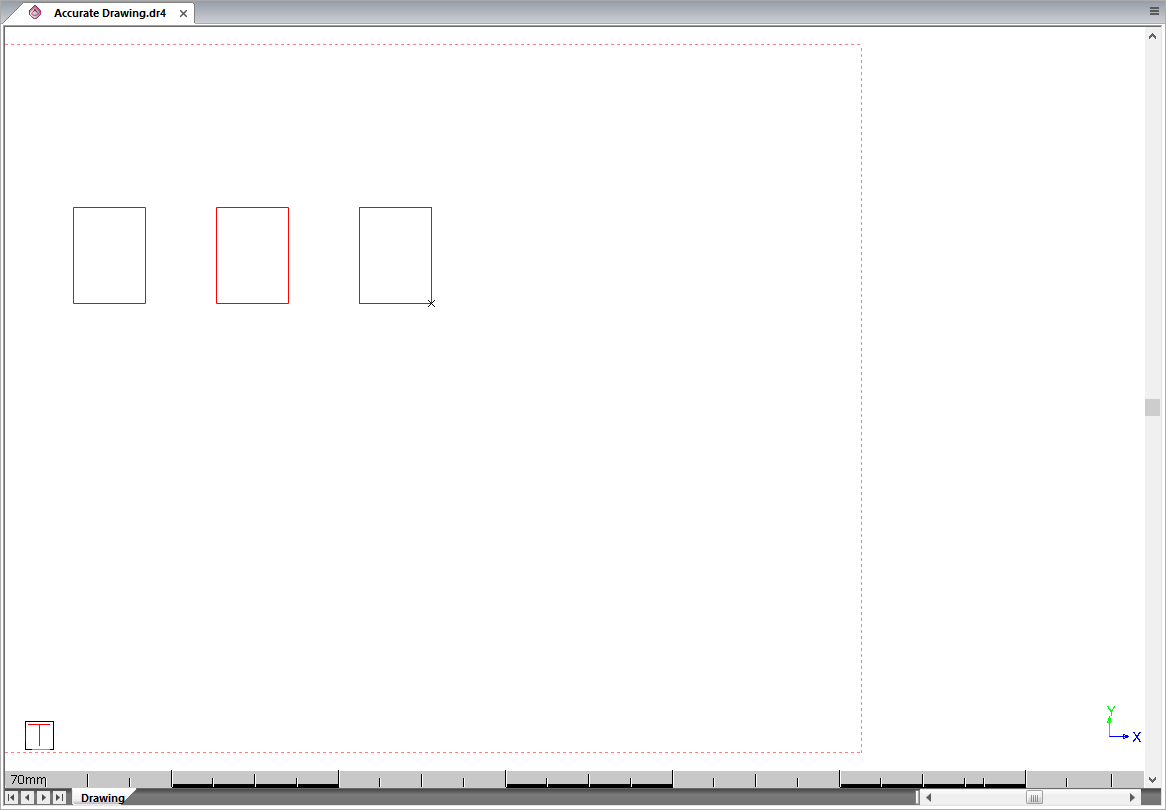
In this section, only locking the cursor into the horizontal and vertical directions is demonstrated. However, the cursor can be locked to any angle and to its orthogonal, as well as into an isometric mode (30, 330 and 90 degrees).
Ignore the prompt for the first rectangle corner and select Draw ► Line.
You are prompted to:
Indicate start position of line
Click the Coordinate Jump icon.

Type “60 80” and press [Enter] to accept these coordinates. The cursor moves to the right of the rectangles you have already drawn.
Indicate end position of line
Press [Shift+Right-Arrow] to move the cursor 30mm to the right. Press [Enter] to accept the horizontal line that is drawn.
Indicate start point of line
 on
the Snaps toolbar or press [Shift+A].
on
the Snaps toolbar or press [Shift+A].Do not worry about the fact that the line you are drawing follows your cursor as you click the icon in the toolbar. When you have clicked the icon, move your cursor back to the area of the screen where you are drawing.
When the cursor is a square you are in Grab All mode. This means that the cursor will automatically jump to any point within the cursor box.
You are now going to lock the cursor
so you can only draw horizontally or vertically. Click the Lock Perpendicular
icon  in the Lock Cursor toolbar. Alternatively,
press [+] on your numeric keypad or select Tools
► Lock Cursor ► Perpendicular.
in the Lock Cursor toolbar. Alternatively,
press [+] on your numeric keypad or select Tools
► Lock Cursor ► Perpendicular.
A diamond shape appears inside the box that represents the cursor. Click inside the cursor box and then use your mouse to pull the cursor downwards. The line that is drawn is vertical and straight. When the line reaches the level of the bottoms of the rectangles you have already drawn, move your mouse to the left. The square representing the cursor separates from the diamond. Move the cursor so that the bottom right hand corner of the right hand existing rectangle is within the cursor box.
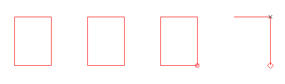
Click and the square cursor jumps back to the diamond shape and the vertical line has been terminated so that it is exactly the same length as the vertical lines of the other boxes. Press [Enter] to accept the line.
Now move your cursor through the cursor lock indicator. When you do so, the cursor lock switches between vertical and horizontal.
With the cursor movement locked into horizontal mode, place the cursor box around the end of the top line and press [Enter] or click. The cursor box springs back and the bottom line of the box is drawn to exactly the right length. Press [Enter] to accept the line.
To finish the box, move your mouse upwards so the cursor box surrounds the end of the top line again. Press [Enter] or click to complete the rectangle.
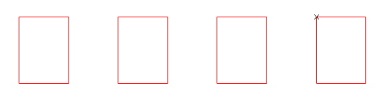
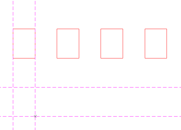
In this section you are going to draw some geometry lines and use these to draw a box. The lines you are going to draw will be very simple.
Select Geometry ► Cross.
Indicate cross position
Click the Jump Coordinate icon.

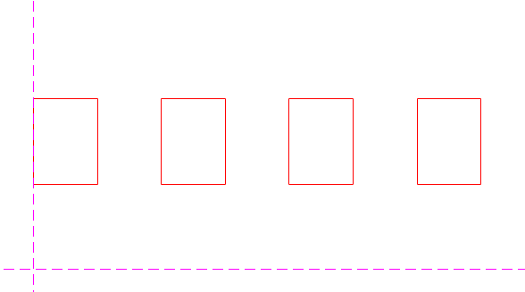
Indicate cross position
Press [Shift+PgDn]. The CAD automatically moves 30mm to the right and 40mm down, which are the distances you have been using throughout this tutorial.
Indicate cross position
Ignore this prompt and click the
Rectangle icon  .
.
Indicate first corner of rectangle
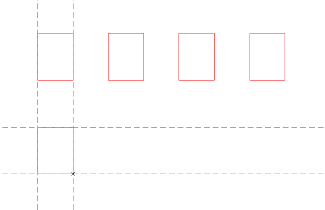
Position the cursor near the top left intersection of the geometry lines and then click. The first corner of the rectangle is defined.
Indicate second corner of rectangle
Move the cursor close to the intersection to the bottom right of the geometry lines as shown below. Click to accept it as the second rectangle corner.
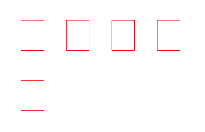
For the present, you will not need the geometry lines you have drawn. Turn them off by selecting Geometry ► Switch Geometry On/Off or by clicking the Geometry Toggle icon. The geometry lines are not displayed.
Now, you are going to draw a rectangle using a regular grid.
Set up the grid display with a pale grey colour and an interval of 30 in the X plane and 40 in the Y plane. This yields a grid with horizontal spacing of 30mm and vertical spacing of 40mm. For convenience, specify that the grid will be drawn as lines.
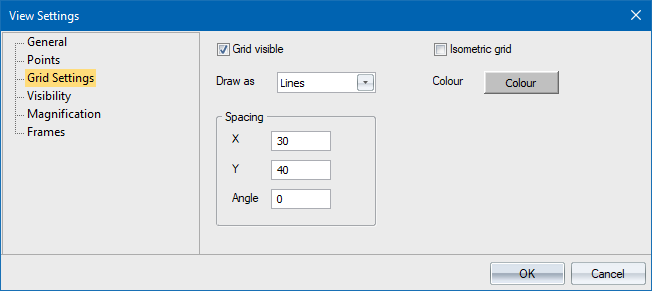
Click OK to display the grid.
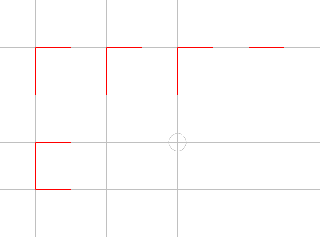
Click the Rectangle icon.
Indicate first corner of rectangle
Press [Shift+G] to activate the Grid Snap mode. Move the cursor to the position shown and click. The cursor jumps exactly onto the nearest grid point and enters the first corner of the rectangle.
Indicate second corner of rectangle
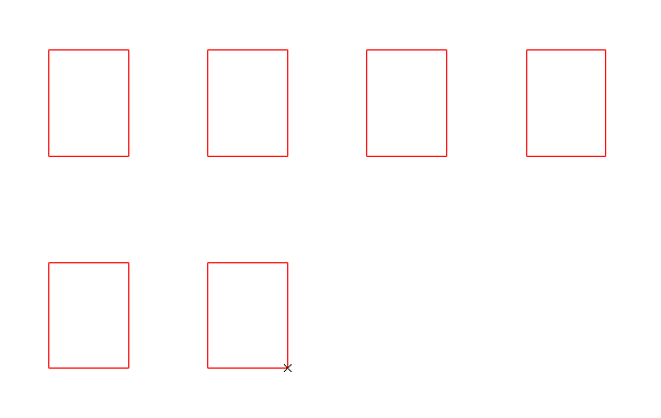
Now move the cursor close to the grid point below and to the right, and then click. The cursor jumps to the grid point and accepts that point as the second rectangle corner.
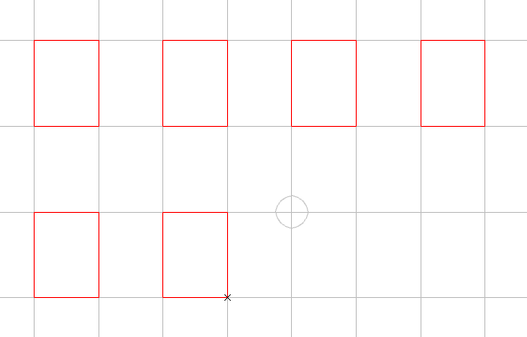
So far you have encountered four types of jumps/snaps.
Key |
Icon
|
Description |
[X] |
|
Makes the cursor jump to the Last Fixed point of the cursor. |
[I] |
|
Makes the cursor jump to an Intersection of geometry lines. |
[P] |
|
Makes the cursor jump to an exact distance in a specific direction. Also known as Polar jump. |
[G] |
|
Makes the cursor jump to a Grid point. |
There are also a number of other jumps.
Key |
Icon
|
Description |
[H] |
|
Jump to the centre of the screen. |
[A] |
|
Jump to anything within the cursor box. |
[J] |
|
Jump to the nearest point e.g. the end of a line, an arc centre. |
[0] (Zero) |
|
Jump to any intersection. |
[N] |
|
Jump to the nearest line or arc. |
[O] |
|
Jump to a fixed ratio between two points which usually defaults to the midpoint. |
[U] |
|
Jump to an exact coordinate location. |
[C] |
|
Jump to the midpoint of the nearest line. |
[*] |
|
Jump to the nearest circle or arc centre point. |
[E] |
|
Jump to a point on the circumference of the nearest circle. |
[V] |
|
Jump to a quadrant point on the nearest circle. |
[F] |
|
Jump a distance from the end of a line in the line direction. |
[Ctrl+I] |
|
Jump to the intersection of any two lines. |
In the Grab All
and Freehand modes you can use any of the jumps listed above.
There are also various snap modes. One of the most useful snap modes is GrabAll snap, which is activated by clicking the GrabAll icon on the Snaps toolbar or pressing [Shift+A].
In Grab All mode, the cursor is a square and automatically jumps exactly to any point within this square each time you press [Enter] or click.
You can specify which points the GrabAll snap will snap to using the GrabAll Settings.
In addition to the Freehand, Grab All and Grid modes, there are also the following snap modes.
Name |
Key |
Icon
|
Description |
Geometry Intersection |
[Shift+I] |  |
Automatically snaps to nearest geometry intersection. |
Point |
[Shift+J] |  |
Automatically snaps to nearest point. |
Nearest Entity |
[Shift+N] |  |
Automatically snaps to nearest element. |
Intersection |
[Shift+Z] |  |
Automatically snaps to nearest intersection. |
Circle Centre |
[Shift+Num*] |  |
Automatically snaps to nearest circle or arc centre point. |
Near Circle Centre |
[Shift+E] |  |
Automatically snaps to the centre point of the nearest circle or arc. |
Apparent Intersection |
 |
Automatically snaps to intersection between entities in 3D space that appear to intersect but are on different planes. | |
Perpendicular |
[Shift+P] |  |
Automatically snaps a line to another line or arc so that they are perpendicular to each other. |
Tangent to Circle |
[Shift+T] |  |
Automatically snaps a line or arc to another line or arc so that they are perpendicular to each other. |
Mid point |
[Shift+M] |  |
Automatically snaps to the midpoint of nearest entity. |
Ratio |
[Shift+C] |  |
Automatically snaps to the ratio of length on entity. |
Note that the
cursor is a different shape in each mode.
Although Geometry Intersection and Grid jumps and snap modes are used in this tutorial, the Grab All mode can also snap to geometry intersections and grid points, as well as to points and intersections.
Some functions automatically switch to Freehand mode, because it is important that the cursor doesn't snap to anything by accident. These include the Coordinate Jump and Polar Jump.
If the visual snap indicator is switched on, the snap points are highlighted with a red rectangle as the cursor gets close to them. You activate the visual snaps by clicking VS in the Status Bar.

You can change the visual snap indicator using the Visual Indicators option of the System Settings.
You can now save your drawing.
Click the Save icon  and type “Accurate Drawing”
as a name for your drawing.
and type “Accurate Drawing”
as a name for your drawing.
Click Save.
You now know how to draw entities accurately.


