Icon
Command
Shortcut Key
Toolbar

DIMTOLERANCE
Dimensions
Create a tolerance annotation.
|
Icon |
Command |
Shortcut Key |
Toolbar |
|
|
DIMTOLERANCE |
|
Dimensions |
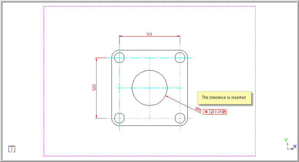
This function allows you to add a tolerance annotation to the drawing by means of the Tolerance Feature Control, which allows you to input the required data.
 The text in the tolerance uses the current text style and height.
Procedure
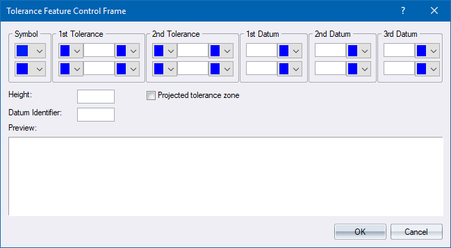
Set tolerance properties
Input the tolerance type, tolerance values and datum information. You can also specify height, projected tolerance zones and datum identifiers. A Symbol can be selected that represents the geometric characteristics to which the tolerance is being applied. As the information is added, the preview is updated to show the tolerance table.
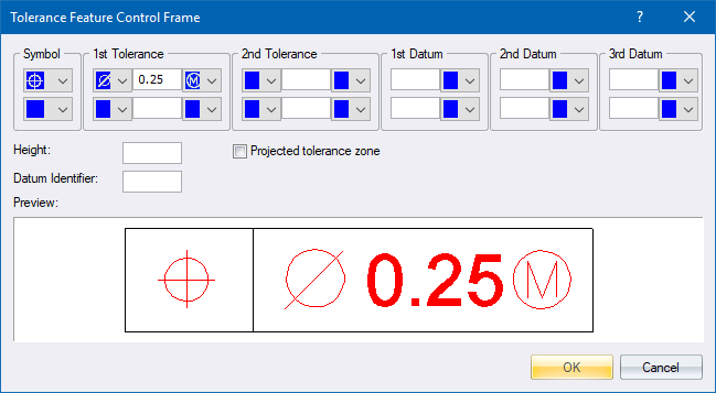
When you have inputted the information, click OK to insert the tolerance in the drawing.
You are prompted to:
Indicate insertion point for the tolerance
The Tolerance table is displayed and you can move it to the required position. Position the tolerance in the required position and click to insert it in the drawing window.
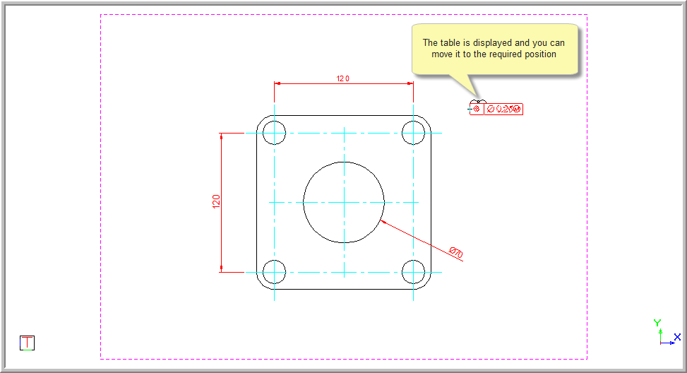
The function repeats, allowing you to add more tolerance frames to the drawing as required.
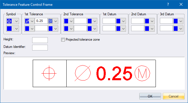
Click Cancel to end the function, or insert any other tolerances you may require.