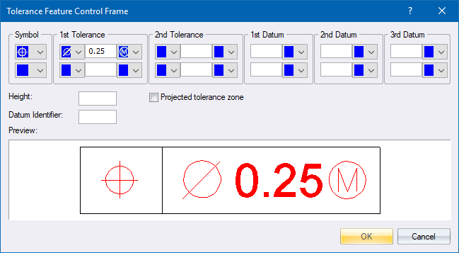
Create or edit a geometric tolerance entity.
|
Option
|
Description |
|
Symbol |
Select a symbol from the dropdown list. This is the tolerance type. |
|
1st and 2nd Tolerance |
Enter the tolerance values. A diameter symbol and modifier symbol can be selected from the left and right dropdown lists respectively. |
|
1st, 2nd and 3rd Datum |
Enter the primary, secondary and/or tertiary datum identifiers. A modifier symbol can be selected from the dropdown list. |
|
Height |
Enter the height offset of the tolerance. |
|
Projected tolerance zone |
Select this checkbox to include the P symbol in the tolerance. |
|
Datum Identifier |
Enter a datum identifier. |
|
Preview |
Displays what the tolerance will look like in the drawing. |
 You can specify a second row of tolerances by entering values in the second row of entries.