Icon
Command
Shortcut Key
Toolbar

VIEWRENDER
Misc
Generate a 3D perspective rendered view of the drawing.
Icon |
Command |
Shortcut Key |
Toolbar |
|
VIEWRENDER |
|
Misc |
This function allows you to generate a 3D rendered view of the drawing with optional light settings. The rendering may take a few seconds for larger drawings.
CAD functions are not active in the Render View.
You can only activate the Render View function in the Drawing layout (drawing space).
 You can use the
Save View function to save the image
of the Render View to an image file.
You can use the
Save View function to save the image
of the Render View to an image file.
Procedure
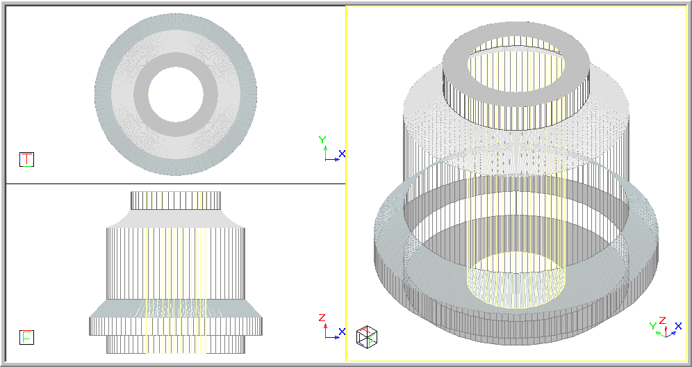
The drawing below shows the front, top and isometric views of a Flange.
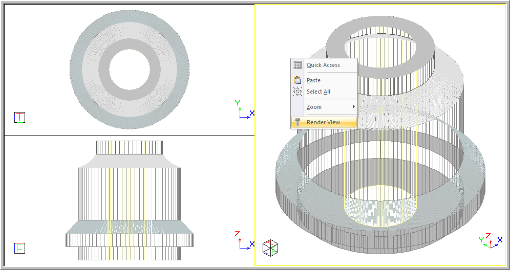
To view the rendered view of a drawing:
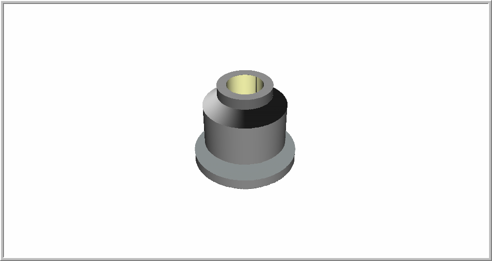
The following navigation controls enable you to explore a drawing in 3D by moving and looking around the drawing in 3D.
Control
|
Description |
Reset |
Click
|
Lighting |
Click
|
Pan |
To strafe left, right, up and down in the current view plane, click and hold while you drag the mouse. This moves the camera in its current viewing plane. |
Zoom |
To
move towards or away from an object or the drawing, rotate the
mouse wheel forwards or backwards respectively. Alternatively,
click You will zoom into the closest object you are zooming into, or if no object is under the mouse it will zoom at a scale relative to the extents of the drawing. |
Rotate |
While holding [Ctrl], drag the mouse to rotate around your drawing. Up-down mouse drags will result in turning the world towards or away from you. Left-right drags result, by default, in spinning the world around the up axis. This default rotation is called Turntable rotation.
An alternative rotation style, called ArcBall, is available. This allows you to rotate the world similar to rotating around a ball. This is similar to pivot type rotation.
To toggle between Turntable and Arcball type rotation,
press [T] in Render View or click The |
Looking Around |
If you are inside a 3D object or world, press and hold [Shift+Ctrl] and drag the mouse. This allows you to look around the drawing. The behaviour is similar to rotating around a scene, however, it is the camera that stays in its fixed position and changes its orientation to look up, down, left or right, i.e. it provides a first-person view. |
Level View |
Click
|
Right-click to bring up the Render View context menu.
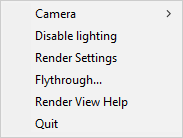
Menu Option
|
Description |
Enable/Disable lighting |
Select this option to enable or disable the lighting.
|
Render Settings |
Select this option to change the Render View Settings for the Render View.
|
Help |
Show render view navigation help.
|
Quit Render View |
Select this option to exit the Render View and return to the CAD view.
|
The flythrough function allows you to move the render view camera along a predetermined path in the drawing, generating an animation that can also be saved to disk as an AVI (video) file.
During a flythrough, you can press [Spacebar] to pause/unpause it. If you want to exit the flythrough before it is finished, press [Esc].
In Render view:
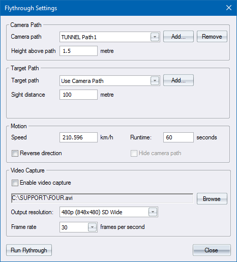
You can select an existing camera path from the Camera path dropdown, or add a new path for the camera. If required, you can also specify a separate path for the target point.
To add a new path:
Click Add in the Camera path section.
When you indicate an entity, you are prompted to enter a name for the new path.
Enter a name or accept the default name.
The Flythrough Settings window reappears with the current camera path set to the path you just created.
If required,you can elevate the camera above the camera path by entering a value in the Height above path field.
Enter a non-zero value in the Sight distance field if you want the camera to look at a point on the target path, which is the specified distance along the path in front of the camera, as it moves.
The speed and run time of the flythrough are inter-related, and are also dependent on the length of the camera path. Setting the speed will calculate a new runtime by dividing the length of the path by the speed; and setting the runtime will calculate a new speed by dividing the length of the path by the runtime.
Enter a speed in the Speed field and then press [Tab]. The Runtime value automatically updates based on the calculated runtime. Similarly, if you enter a run time in the Runtime field and press [Tab] the Speed value automatically updates.
Select the Reverse direction checkbox if you want the camera to begin at the path end point and move towards the path start point.
Select the Hide camera path checkbox if you don't want the entity that you specified as the path to appear in the flythrough.
To capture a video:
Select an output file for the video capture by clicking Browse.
Enter a new filename or indicate an existing .avi file, which will be overwritten.
Select the resolution of the video file from the Output resolution dropdown. A higher resolution results in a larger video file.
Select a video capture frame rate. A higher frame rate results in a smoother video but also a larger video file.
Click Run Flythrough to check that your flythrough settings are correct. If you are happy with the resulting animation, press [Esc] to exit the flythrough.
Select the Enable video capture checkbox and then click Run Flythrough again.
Capturing to higher resolutions and higher frame rates may cause the flythrough
to slow down. The resulting .avi will, however, play back at the correct
speed.
The flythrough paths and settings are imported and exported when loading or saving DWG files.
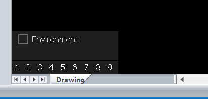
If you are using the hardware accelerated renderer (System Settings ► Hardware Acceleration), the Environment option will be visible in the lower-left of the render view:
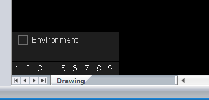
Select the Environment checkbox to display the Environment Settings panel in the top left corner of the Render View:
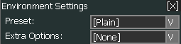
The Environment Settings control the appearance of the "background" in the Render View. These controls can be switche doff by clicking the X in the top right corner of the control. The control can be moved by clicking and dragging the title bar to its desired location.
There are two settings - Presets and Extra Options.
This option provides several skybox styles that you can directly apply to the current scene.
Menu Option
|
Description |
Plain |
This is the default style, which disables the skybox and uses the default background colour from the Render View Settings. |
Custom |
Used for creating a skybox using custom settings. |
Dawn |
A predefined Dawn style. |
Sunny |
A predefined Sunny style. |
Cloudy |
A predefined Cloudy style. |
Sunset |
A predefined Sunset style. |
Night |
A predefined Night style. |
In Custom mode, all skybox settings can be manually customised.
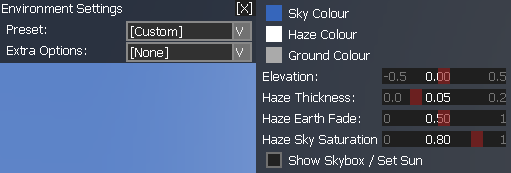
These options allow you to change the colour and style of the skybox. The skybox is a spherical structure, which can be divided into three parts - Sky, Haze and Ground. Each part can have a different colour and they are blended from top down to create a linear colour gradient.
Attributes like the Elevation, Haze Thickness, Earth Fade and Sky Saturation can be tuned directly by dragging the relevant slider. The changes will be applied instantly to the scene in the Render View.
The colours of Sky, Haze and Ground can be changed by clicking on the relevant Colour item. A colour palette will pop up for direct colour picking.
Changes will be immediately visible in the scene. However, you may find it difficult to perceive the result as the current view normally shows a fraction of the skybox. Therefore, we provide the Show Skybox/Set Sun option to visualise the entire skybox with its 6 sides laid out.
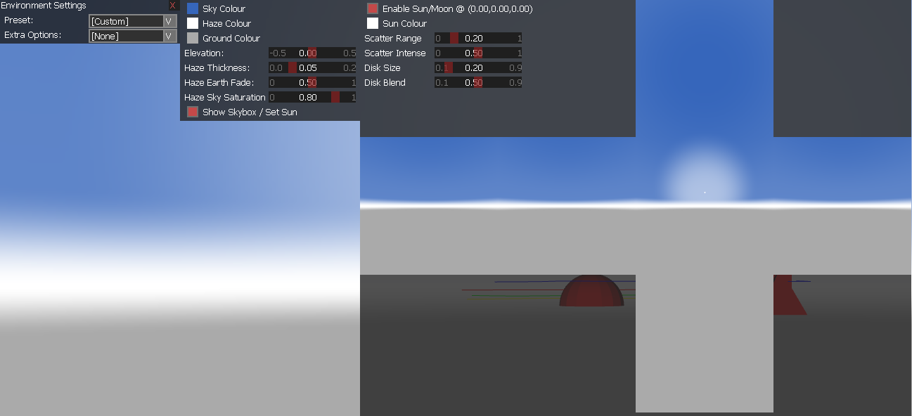
This skybox preview can also be used to set the psotion of the sun (or moon) in teh sky. Click in the skybox preview to set the position of the sun directly.
This option provides extra effects for the "ground plane", such as a checker board or an ocean simulation.
Menu Option
|
Description |
| None | The default value, which disables the extra options and hides the Altitude slider bar. |
| Custom | You can use this option to customise the ocean settings with desired colour and wave type. |
| Wireframe | A predefined ocean rendering in Wireframe mode. |
| Checkerboard | A predefined Checkerboard style. |
| Rough Ocean | A predefined water simulation with a rough surface. |
| Calm Lake | A predefined water simulation with a calm surface. |
Custom provides a set of parameters to help the creation of a water surface with desired roughness level. All adjustments take effect immediately.
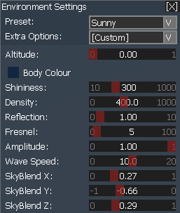
Custom,
Rough Ocean and Calm
Lake modes will trigger animated rendering, which means the CPU
and GPU eill be constantly processing and rendering the animation when
these modes are selected.
Shortcut views can be accessed in three ways:
Accessing the right-click menu where you can view all shortcut views clearly as a thumbnail. This doesn't provide an Overwrite/Remove option.
Looking at the bottom left bar (numbers 1-9) where you can check if a shortcut view is assigned. This doesn't provide an Overwrite/Remove option.
Pressing the number keys (1-9) for fastest access.
If you are using the hardware accelerated renderer, the Shortcut views (numbered 1 to 9) will be visible in the lower-left of the render view.
Click on any of the shortcut view numbers to store the current view as a shortcut view. A tiny thumbnail image of the stored view will be drawn underneath the number, in this case shortcut view 2.
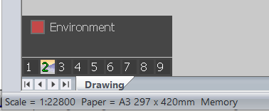
If you change the view rotation or pan the view to a new position, you can at any time switch back to the stored view by clicking on the shortcut view number.
To overwrite the stored view with the current view, press [Ctrl] and click the shortcut view number.
The shortcut views are also available from the right-click menu, and work in the same way, but have larger thumbnails images.
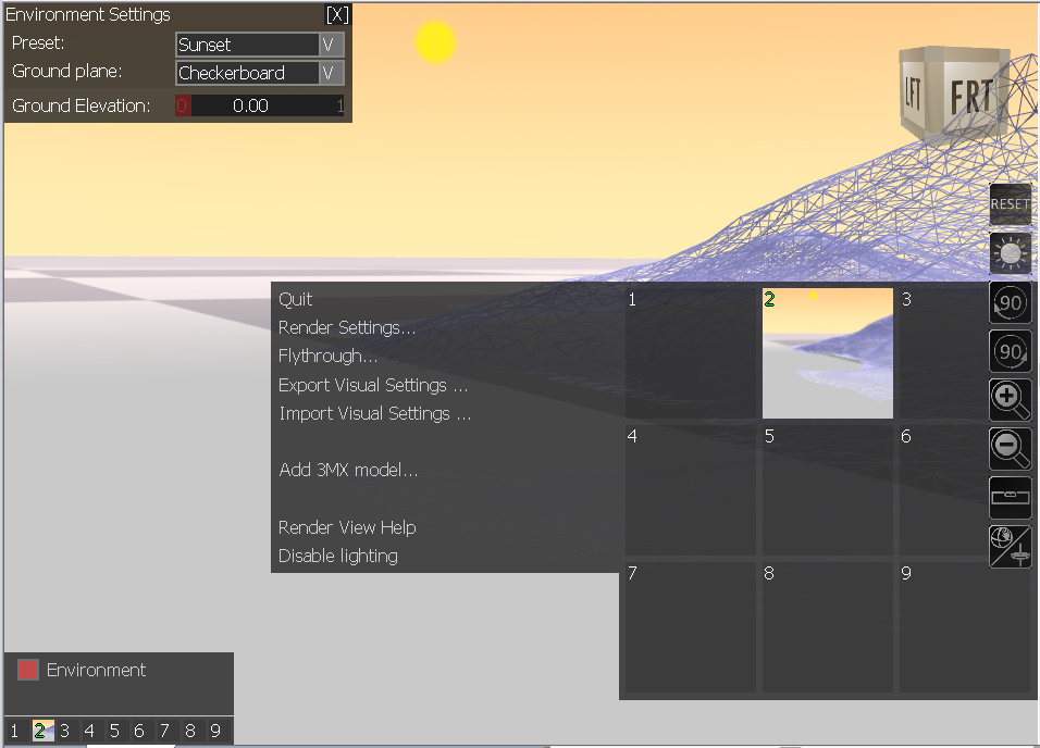
The context menu in Hardware Accelerated mode provides a convenient way to access the Render View functions that are only available in Hardware Accelerated mode. You can access these features by right-clicking in the Render View:
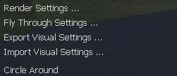
Menu Option
|
Description |
Render Settings |
Opens the Render View Settings dialog box. |
Fly Through Settings |
Opens the Fly Through Settings dialog box, allowing you to set up a flythrough. |
Export/Import Visual Settings |
Opens a dialog box to help export/import the current visual and environmental settings, such as Skybox colours, ocean style, terrain mode, etc. This file (.vis) is actually a text file, and can be used to share the current Render View visual settings to multiple users. |
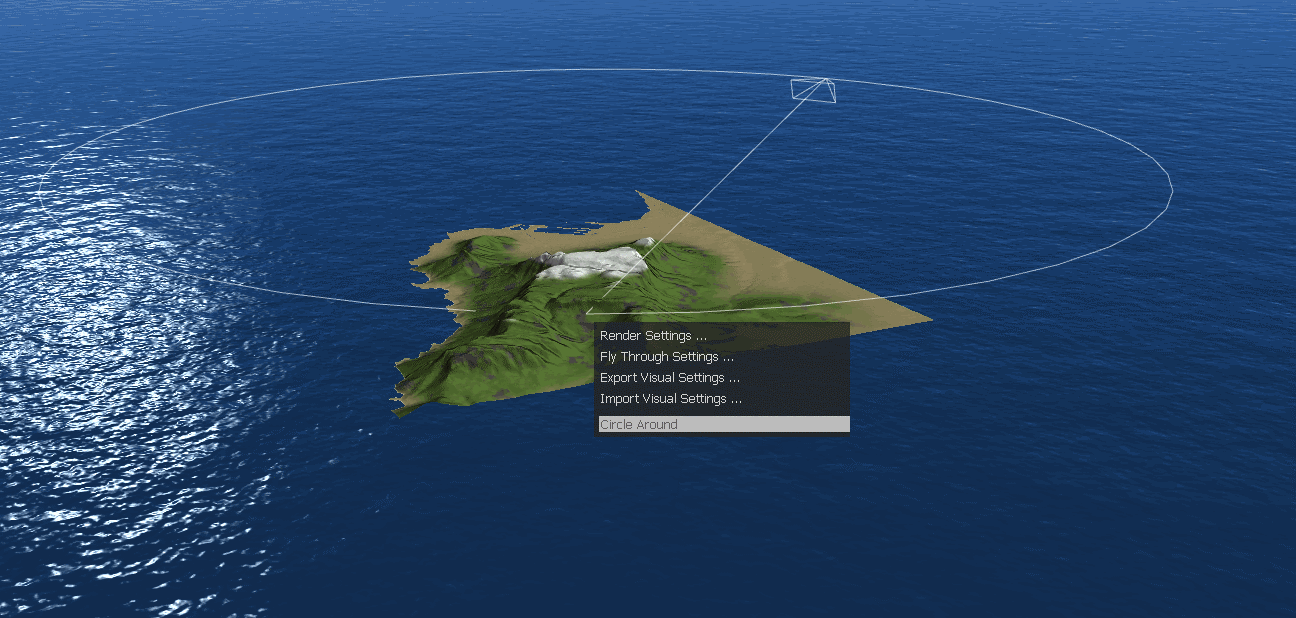
Circle Around |
A camera animation that provides a 360 degree overview of the clicked object. The object in the scene that you right-clicked on is used as a target point for the camera. The camera will rotate a full 360 degrees around this target point, by default taking about 8 seconds for a full rotation. Note that the camera always spins around the Z axis and its radius is calculated automatically depending on the picking position and the current view direction. When the mouse is moved over the Circle Around option, a quick "path review" will be displayed in the Render View to help visualise how the circle operation is going to work. You can pre-adjust the Circle Around time in the Render View Settings dialog.
|
Besides the Circle Around operation, right-clicking in the scene also detects nearby Lines/Polylines/Arcs and Road Entities that could be used for a flythrough, and provides a Fly Along option as shown below.
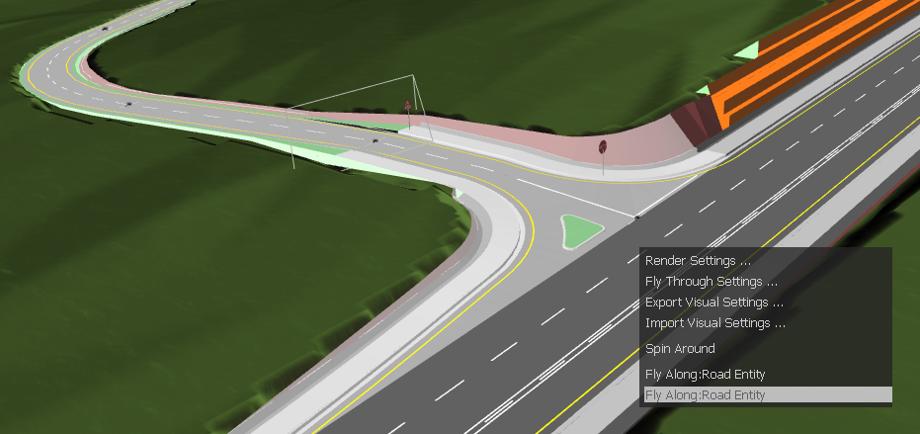
A "quick path preview" will also be displayed when you hover over the Fly Along option. Note that Road Entities behave a bit differently from the other entities that can be used for Fly Along, particularly with the calculation of total flight time. The following table shows these differences:
| Line/Polyline/Arc
|
Road | |
| Total Flight Time | 8 seconds | From Flythrough Settings |
| Reverse Direction | From Flythrough Settings | From Flythrough Settings |
| Height Above Path | From Flythrough Settings | From Flythrough Settings |
While a fly-through is running, real-time controls are displayed onscreen to help adjust the speed, camera offset, and view direction on the fly:

The following table lists the controls available:
| Easiest
Method
|
Alternatives | |
Adjust speed |
Scroll Mouse |
Click Decrease/Increase buttons on screen. |
Adjust the camera horizontal offset |
Press [Left Arrow]/[Right Arrow] |
Click Left/Right buttons on screen. |
Adjust the camera vertical offset |
Press [Up Arrow]/[Down Arrow] |
Click Up/Down buttons on screen. |
Change the view Direction |
Toggle [V] and mouse moves |
|
There are no real-time
controls for the Circle Around
function. You can pre-adjust the Circle
Around time in the Render
View Settings dialog.
 to reset your
view direction to its original direction when entering Render
View.
to reset your
view direction to its original direction when entering Render
View. to toggle lighting
on/off.
to toggle lighting
on/off. or
or  to zoom in and out,
respectively.
to zoom in and out,
respectively. .
. and
and  buttons allow you to
turn the object/drawing 90
buttons allow you to
turn the object/drawing 90 to adjust the
object/drawing so you can get a horizontal view of it from the
camera. This is useful if you have twisted the object/drawing
while zooming/viewing it.
to adjust the
object/drawing so you can get a horizontal view of it from the
camera. This is useful if you have twisted the object/drawing
while zooming/viewing it.