Icon
Command
Shortcut Key
Toolbar
![]()
DIGISETUP
Settings
Configure the program to use a digitiser for drawing, instead of the mouse.
|
Icon |
Command |
Shortcut Key |
Toolbar |
|
|
DIGISETUP |
|
Settings |
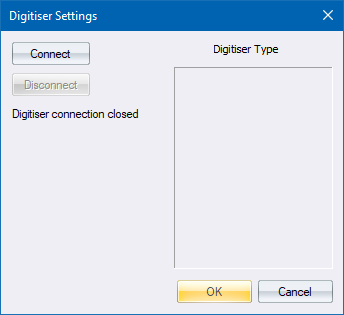
This function allows you to configure the program to use a digitiser for drawing, using the Digitiser Settings.
 Before using the digitiser, you must install the Tablet Control drivers for the digitiser. This driver has an application for testing the digitiser, and it is advisable that you confirm the digitiser is working before trying to use it. Digitiser connections can be unstable. If the digitiser is not picked up or stops working, you may need to reset the connection from the Tableworks driver program. It may also be necessary to physically disconnect the digitiser or restart the program.
Procedure
To configure the program to use the digitiser for drawing:
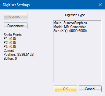
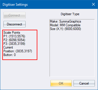
You now need to click on three points on the digitiser, which are used to calibrate the digitiser coordinates to the CAD coordinates. The points are chosen by clicking Button 1 on the digitiser in each of the three locations. The number of the button is shown in the window so you can confirm which is Button 1. The order of the points doesn’t matter, so long as you select the CAD points in the same order as the digitiser points.
When the points are selected, click OK. If you click Cancel, the digitiser drawing mode is not entered and the user continues drawing with the mouse.
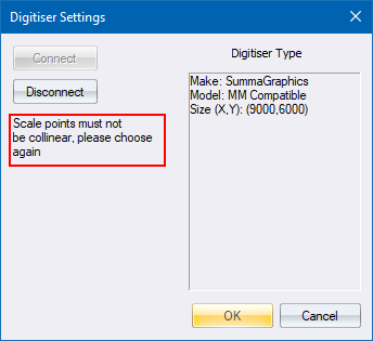
The three points must not be co-linear. If co-linear points are selected, an error message displays. You must move the digitiser to select all three points again.
If the three points are acceptable, you are prompted to choose the corresponding points in AllyCAD.
You are prompted to:
Click on first corresponding Point in Drawing
Choose the point in the CAD that corresponds to the first digitiser point.
After this you are prompted for the second and third points, and must enter the CAD points that correspond to the second and third points enter on the digitiser.
After the third point is entered, the digitiser becomes active and you can use it to trace. Button 1 corresponds to a mouse click. Button 2 corresponds to pressing [Esc] or [Spacebar]. Any other buttons the digitiser has can be configured to use any function you like by editing the file “cad.dig”. The file is in the normal Knowledge Base Software\AllyCAD 8.0 configuration folder. The default is for Button 3 to start the “Draw Chained Lines” function and Button 4 to start the “Draw LW Polyline” function. When drawing, the plane of the digitiser corresponds to the current drawing plane, so you can draw on any plane in 3D using the digitiser by changing the current DP.