Icon
Command
Shortcut Key
Toolbar

SPLINE
Drawing
Draw a smooth curve that passes through a series of points.
|
Icon |
Command |
Shortcut Key |
Toolbar |
|
|
SPLINE |
|
Drawing |
This function allows you to draw a spline by entering the points the spline curve must pass through.
The smooth curve created is known as a Nonuniform Rational B-Spline (NURBS).
An existing spline can be edited by selecting it and then choosing edit options from the right-click context menu.
 The drawn spline function creates a spline using fit points, but there is also full access to the control points and weight available through the Property Bar.
Procedure
To draw a smooth curve to pass through a series of points:
Select Draw ► Splines or click the icon in the Drawing toolbar.
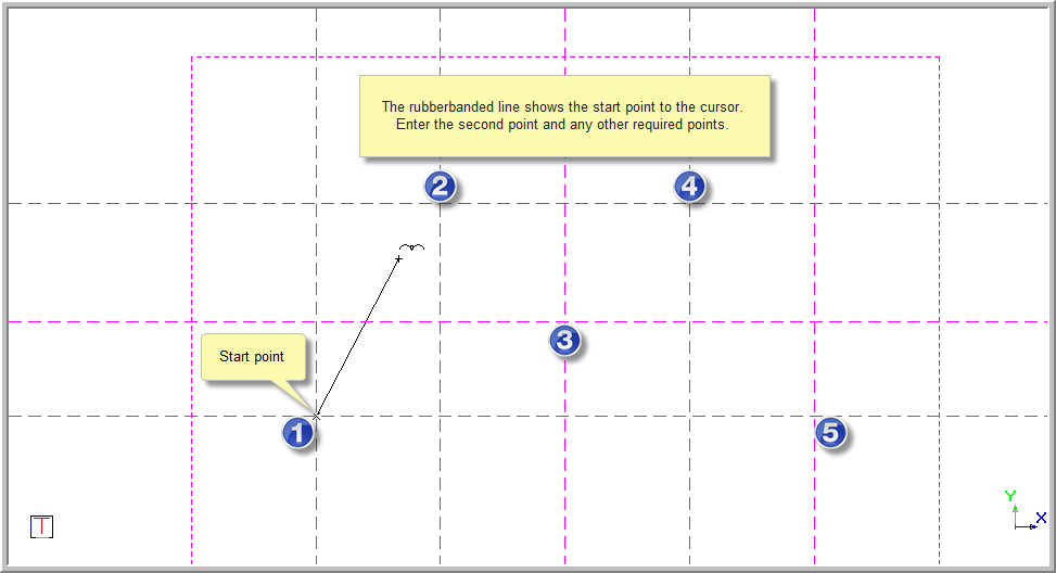
Indicate first point
Position the cursor over the desired start position and click or press [Enter].
Indicate second point
A rubberbanded line shows.
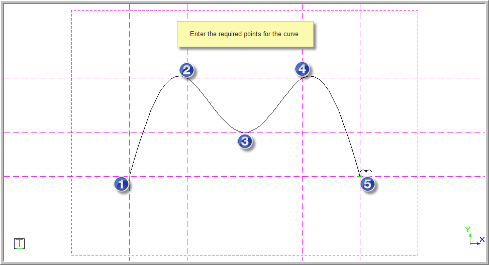
Indicate next point (Right-click to end)
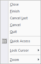
Indicate tangent
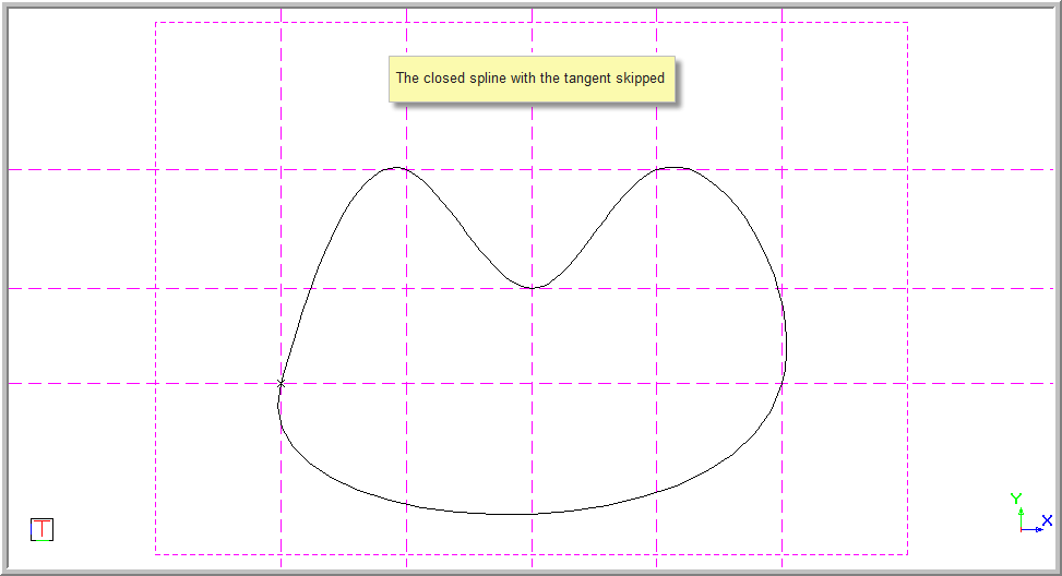
To maintain continuity, the start and end tangent are the same for a closed spline.
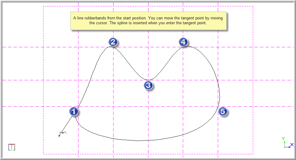
The spline is now drawn in as shown below.
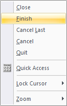
You can select Finish when you have completed entering the fit point and do not want the spline to be closed.
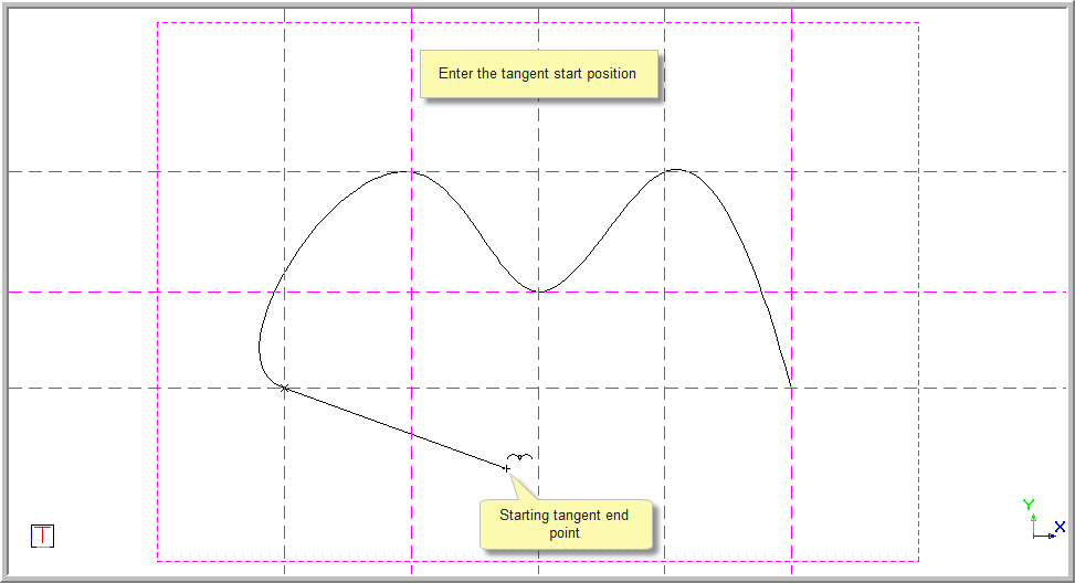
Indicate starting tangent
The rubberband shows a line from the start of the spline to the cursor representing the tangent at the start of the spline. The spline updates to show how the tangent affects the final entity as the cursor is moved.
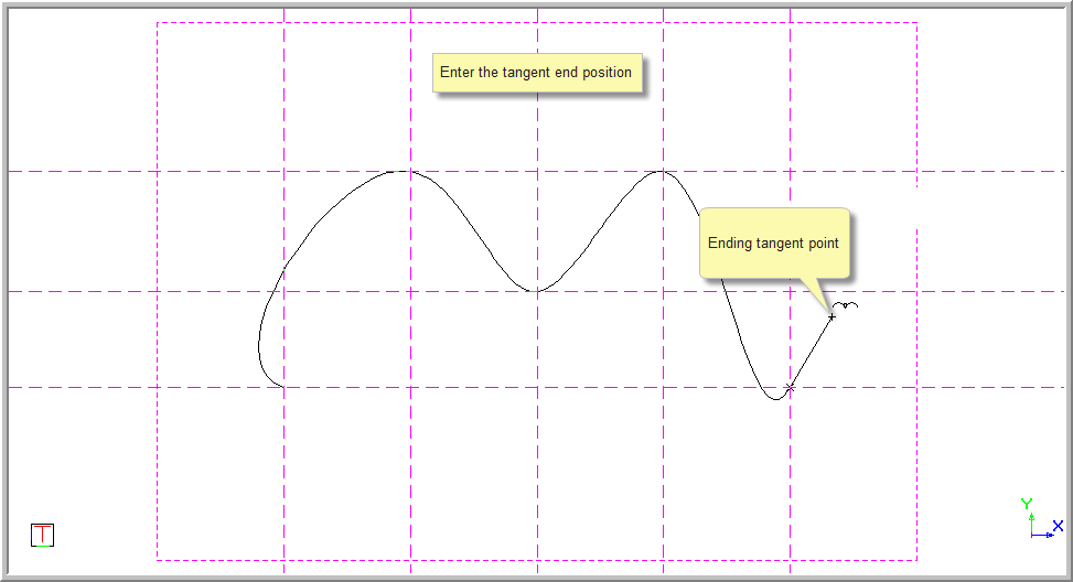
Indicate ending tangent
The rubberband shows a line from the end of the spline to the cursor representing the tangent at the end of the spline. The spline updates to show how the tangent affects the final entity as the cursor is moved.
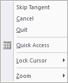
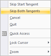
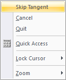
You can also right-click on the screen after selecting finish and select Skip Start Tangent, Skip Both Tangents or Skip End Tangent from the Context menu.
The first two are available from the Context menu when choosing the start tangent and the last when choosing the end tangent.

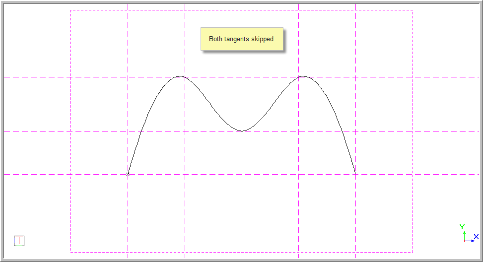
The function repeats and you can start drawing the next spline.
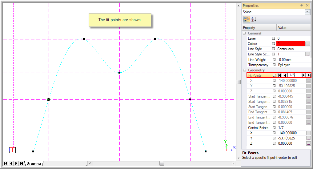
You can now double-click the spline to open the Properties window. Here you can edit the Control Points and Fit Points of the spline, as well as the Weight.
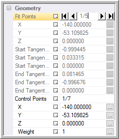
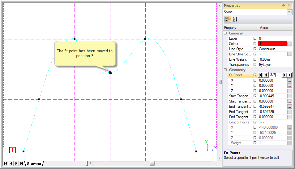
Here the Fit Point has changed to position 3.
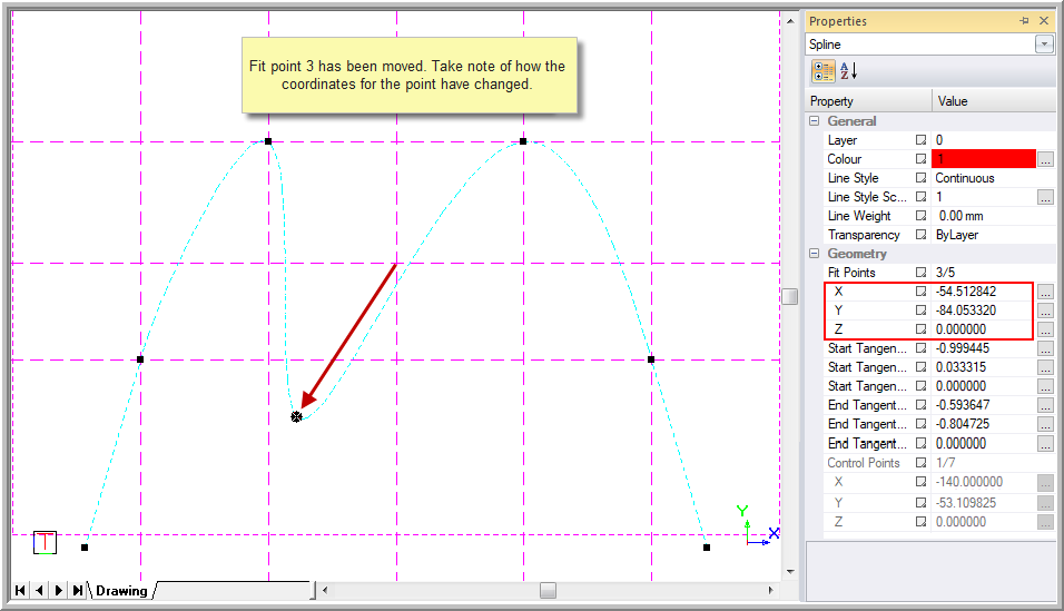

This allows you to edit the Control Points, as shown below.
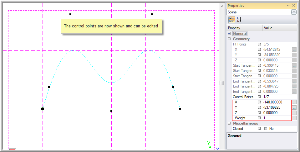
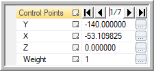
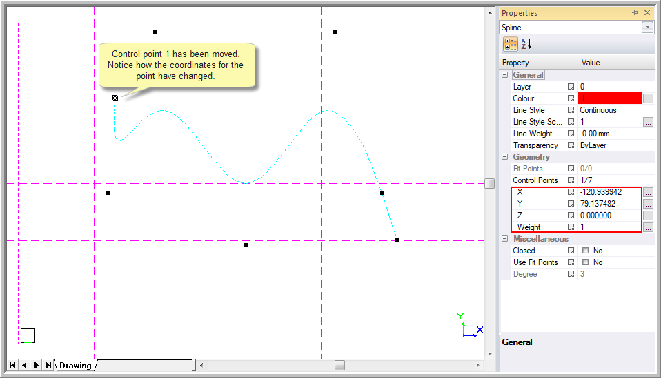
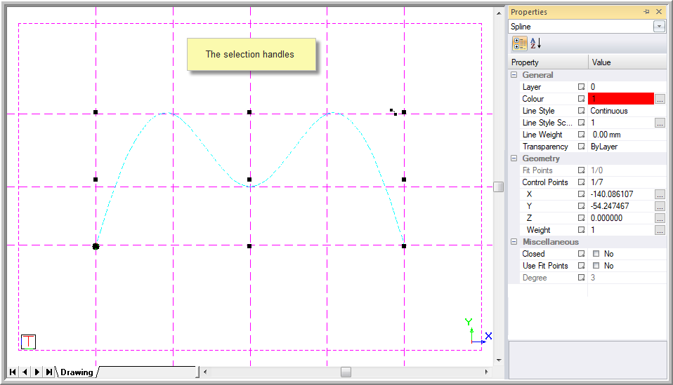
If you click on the Control Points text in the Properties window, spin arrows appear. You can change the position of the Control Point using the spin arrows and edit any of the Control Point's X,Y or Z coordinates in the Properties window. Select the point to edit and type the new position, or click and drag any of the Control Points on the screen to a new position, as shown below.
This changes the curve of the spline.
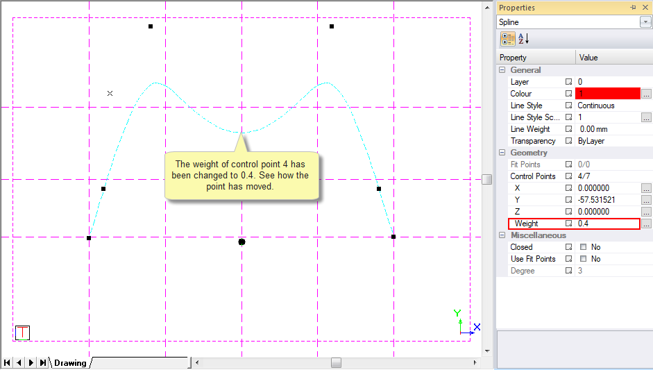
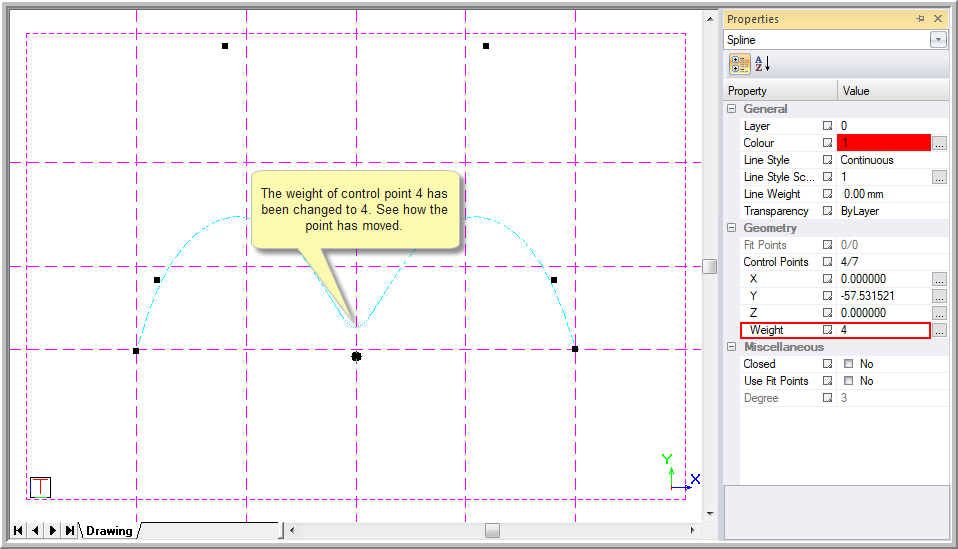
The Weight of Control Point 4 has been changed to 4 in the below example. Note the difference.
The following options are used to edit an existing spline.
Select the spline entities you created by clicking near it.
Right-click and select Append Fit Point from the popup menu.
Click on your desired location and a new fit point is created, which extends the original spline. The updated spline is extended either from the beginning or the end of the spline with regard to which end of the spline is closer to the left-click point.
Right-click and select Quit from the popup menu to finish this operation.
This function is invalid for a closed spline.
Select the spline entities you created by clicking near it.
Right-click and select Insert Fit Point from the popup menu.
Click on your desired location and a new fit point is inserted inside the spline. The shape of the spline is updated accordingly.
Select the spline entities you created by clicking near it.
Right-click and select Remove Fit Point from the popup menu.
Click around the fit point you want to remove. The shape of the spline is updated accordingly.
This function is invalid for a spline with less than three fit points.