3 Point
Add angular dimensions by specifying the centre point and the two angle
end points.
Icon |
Command |
Shortcut Key |
Toolbar |

|
DIMANGULAR3POINT |
|
Dimension |
This function allows you to add an angular dimension
by selecting the centre point and then the two angle end points for the
entity to be dimensioned. Thereafter, indicate the position for the text
to be placed.
You can use the radio buttons in the Control Bar to specify a dimension
style (Free, Chained
and Running).
 Dimensions use
the current line style.
Dimensions use
the current line style.
Procedure
- You are prompted to:

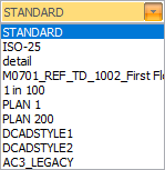
- The dimension style can be selected from the Style dropdown list.
Alternatively, click
 to change the Dimension
Style.
to change the Dimension
Style.
You can click
Pick
to copy dimension settings from an existing dimension entity.
Use the radio buttons in the Control Bar to select
the style for the dimension.

Select the Autospace checkbox to space the
dimension line at a fixed distance from the dimensioned line or arc.
The auto-space distance (in mm on paper) is shown in the edit input
just to the right of the checkbox. You can use this to adjust the
auto-space distance. When auto-space is active, the position of the
dimension line will be locked to the specified distance away from
the dimensioned points.
Check the Text
override checkbox if you want to be able to edit the dimension
text.
Free Dimension
Style
- Position the cursor at the centre point of the arc you want to
dimension. The Point snap mode becomes active.
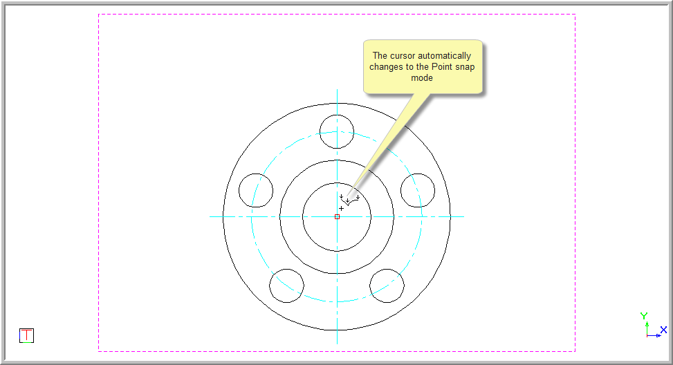
Press [Enter] or click.
- You are prompted to:

- A line rubberbands from the centre point. Press [Enter] or click.
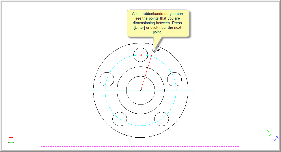
- You are prompted to:

- A line rubberbands from the centre point. Press [Enter] or click
over the second point.
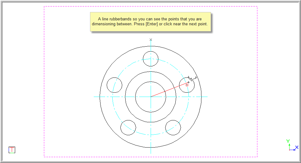
- You are prompted to:

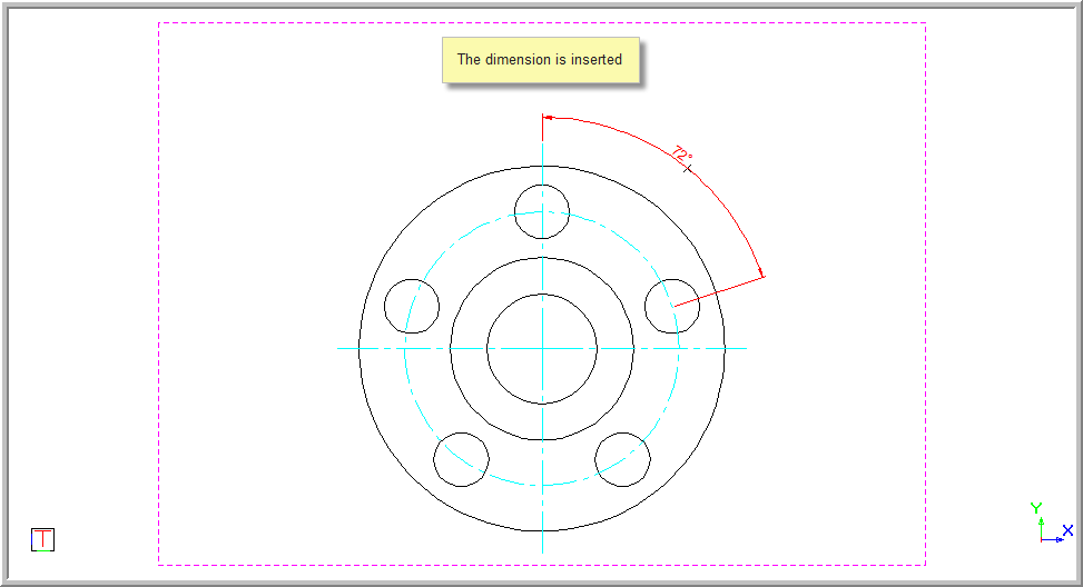
- A rubberbanded preview of the dimension is drawn and you can move
the mouse to indicate the dimension offset. Press [Enter] or click
in the desired position.

If you have selected the Text
override option, you will be prompted to type over the dimension
text. Press [Enter] or click Enter
to insert the dimension.
If the Text
override was not selected, the original measurement will be
inserted and you will again be prompted to indicate the centre point
as before.
- You can continue to add dimensions as the function repeats.
- Right-click and select Quit to end
the function. Alternatively, press [Esc].
Chained
Dimension Style
The Chained
option works in the same way as the Free
Dimension option. The difference is the dimensions follow
on from the last indicated point.
- You are prompted to:

- Position the cursor at the centre point of the arc you want to
dimension. The point snap mode will be active.
Press [Enter] or click.
- You are prompted to:

This determines the angle.
A line rubberbands from the centre
point. Press [Enter] or click.
- You are prompted to:

This indicates the angle.
- A line rubberbands from the centre point. Press [Enter] or click
over the second point.
- You are prompted to:

- A rubberbanded preview of the dimension is drawn and you can move
the mouse to indicate the dimension offset.
- Press [Enter] or click in the required position and the dimension
is inserted.
Remember if you have the Text
override selected you will be able to change the text value.
The rubber banded
preview is drawn.
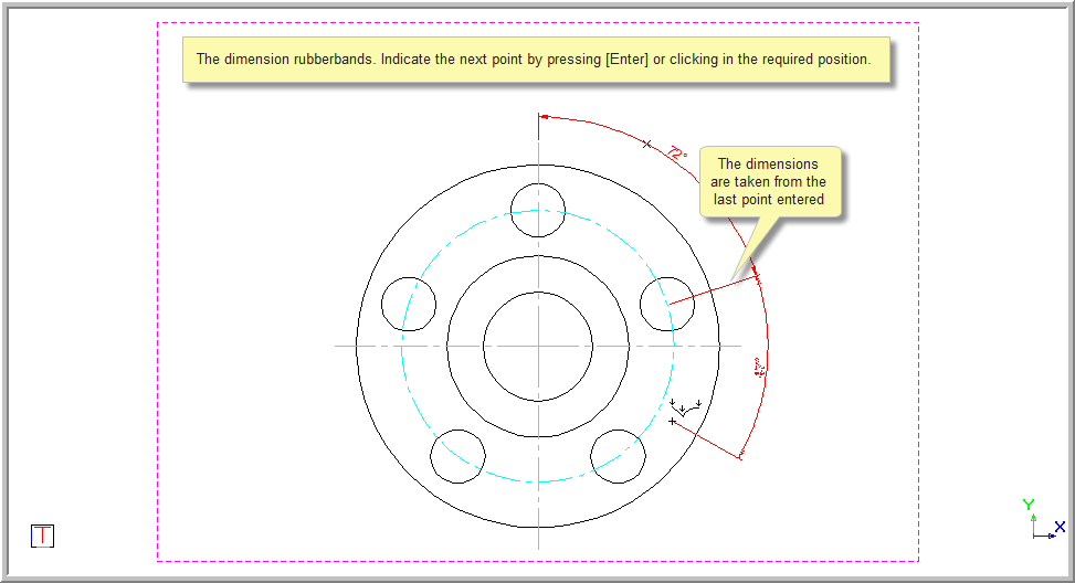
- You are prompted to indicate the next point that defines the second
angular dimension.

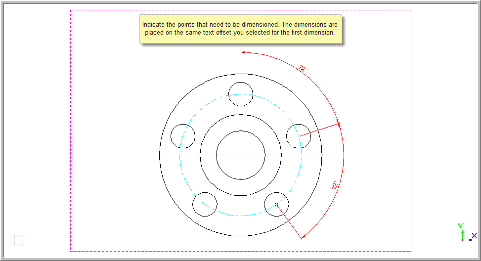
- Continue to enter the points as the function repeats. The dimensions
are placed at the same offset as you selected when placing the first
dimension. Each new dimensions start point is the end point of the
last dimension.
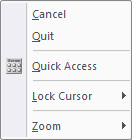
- Right-click and select Cancel to discontinue
with the current alignment and continue dimensioning using a new starting
point. Alternatively. select Quit or press
[Enter] to end the function completely.
Running
Dimension Style
The Running
option works in the same way as the first two options. The difference
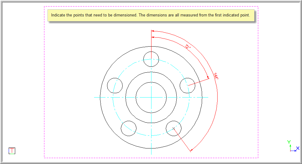
is the dimensions are always taken from the very first point indicated.
- You are prompted to:

Press [Enter]
or click.
- You are prompted to indicate the first point that determines the
start of the angular dimension.

A line rubberbands from the centre
point. Press [Enter] or click.
- You are prompted to indicate the next point that defines the angular
dimension.

- A line rubberbands from the centre point. Press [Enter] or click
over the second point.
- You are prompted to:

- A rubberbanded preview of the dimension is drawn and you can move
the mouse to indicate the dimension offset. Press [Enter] or click
in the required position and the dimension is inserted.
Remember if you have the Text
override option selected, you will be able to change the text value.
- The rubberbanded preview is drawn.
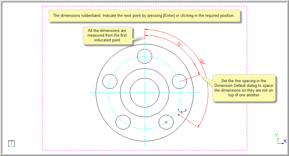
- You are prompted to indicate a point that defines the second angular
dimension as measured from the initial point.

- Continue to enter the points as the function repeats. The dimensions
are placed at the same offset as you selected when placing the first
dimension. Each new dimensions start point is the end point of the
last dimension.
- Right-click and select Cancel to
discontinue with the current alignment and continue dimensioning using
a new starting point. Alternatively, select Quit
or press [Esc]
to end the function completely.