Your layout may not look exactly like this as we have enabled a number of optional items in order to display the relevant screen elements.
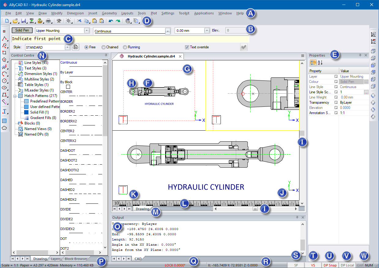
The image below shows the program interface.
Your layout may not look exactly like this as we have enabled a number of optional items in order to display the relevant screen elements.
Specific areas of importance have been marked on the image. Clicking on the letter markers will jump to the corresponding description on this page.
|
Marker |
Screen Element
|
Description |
|
Menu |
Access various program functions by selecting menu items. Top |
|
|
Pen, Layer, Line Style, Width and Height |
These are buttons, combo boxes and edit fields where you can change drawing settings on the fly. Top |
|
|
Prompt/Bar Area |
This area displays prompts while working or, for more complicated procedures, displays a combination bar consisting of its own prompt area and various buttons, etc. for configuring settings while working. An example of such a bar is shown below:
It is always attached to the top of the main window below the top toolbar(s). Top |
|
|
Drawing Area |
This is where all drawing takes place. If the drawing area is subdivided into view ports, the active viewport (the one you can draw in) is outlined in yellow. Top |
|
|
Toolbars |
These are user-defined bars containing shortcut buttons for the various functions. Toolbars can be docked on any edge of the main window, or can be floating. Some of the buttons on the toolbars have additional toolbars called flyout toolbars that can be activated by clicking and holding the left mouse button on the toolbar button, or by right-clicking on the toolbar button. These are indicated by black arrows in the corner of the button. If the mouse cursor is hovered over a toolbar button a help description for that button is displayed in the Scale/Paper Indicator area and, if held over the button long enough, a tooltip window also displays. Top |
|
|
Properties Bar |
This is used to quickly change various properties of the currently selected entity or entities. If no entity is selected, the Property Bar shows,and enables changes to, the current drawing settings (Pen, Layer, Line Style, Width and Height). |
|
|
Paper Border |
This indicates the extent of the defined paper. You would normally draw within this paper extent in order to correctly position your drawing when printing. Top |
|
|
Last Snap/Jump Indicator |
This cross marks the last position where some sort of snap or jump was completed. It is the start position when moving the drawing cursor via the arrow keys or a polar jump. Top |
|
|
Scrollbars |
Use the scrollbars to pan the drawing vertically or horizontally by half the screen for every click. Top |
|
|
Drawing Plane Indicator |
This is similar to the View Plane Indicator but it uses coloured arrows to indicate the relevant axes. It relates to the plane on which drawing is currently taking place, which is not necessarily the same as the view plane. For instance, the view of a house might be set to the southeast corner but you want to draw a door in the left side wall. In this case, the drawing plane would be set parallel to the wall and therefore does not match the view plane. Top |
|
|
Ruler |
This gives an indication of the current scale of the drawing, or the active viewport. This is the normal view:
This following displays if you are working on a layer with a magnification factor:
The second value ("/10") shows the effective scale of the magnified layer while the first value continues to display the global drawing scale. The Scale Bar also displays in green if you are working on a magnified layer. Top |
|
|
View Plane Indicator |
Being a 3D CAD, your view of the drawing can be rotated to any angle. This indicator, which is a cube with sides marked T (Top), F (Front) and L (Left), gives you an idea of the current rotation of the drawing axes. Top |
|
|
Drawing/Layout Tabs |
For each drawing, AllyCAD allows one drawing page and multiple layout pages. Layout pages are used for printing and normally contain some sort of view of the data in the drawing page. These tabs are used to switch between the drawing page and any existing layout page. Right-clicking one of these tabs opens a menu with options to insert new layout pages or to delete existing layouts. Top |
|
|
Control Centre |
This bar displays information relating to the current drawing. |
|
|
Output Bar |
This bar is used to display information relevant to certain tasks carried out. Top |
|
|
Scale/Paper Indicator |
AllyCAD works in a particular scale on a particular paper size, both of which are user selectable. This indicates the scale and paper size that have been selected. Top |
|
|
Lock Indicator |
The current cursor lock angle, if any, is displayed here. Top |
|
|
Cursor Coordinate |
This displays the current position of the mouse or digitiser cursor in X (horizontal), Y (vertical) and Z (elevation) planes. Top |
|
|
Filter Toggle |
This toggles the selection filter on or off. When toggling on, the entity selection filter is displayed, which allows you to specify in detail what types of entity can be part of a selection set. Top |
|
|
Visual Snap Toggle |
This toggles the display of the Visual Snap indicator. When using a drawing function in conjunction with a snap mode (other than Freehand Snap) with this toggled on, a small marker is displayed to indicate where the snap point would be if you clicked with the left mouse button or the first digitiser button. Top |
|
|
DP/3D Snap Toggle |
This toggles between snapping on the current drawing plane and snapping to a 3D coordinate. Normally the snap modes pick up the current elevation from the entity on which the snap is made. With DP Snap toggled on, the elevation is determined by projecting the snap point onto the drawing plane. Top |
|
|
DP/World Coordinate Toggle |
This toggles the Cursor Coordinate between displaying coordinates relative to the current drawing plane and true 3D coordinates. Top |
|
|
Keyboard Indicators |
Shows whether Caps Lock and Num Lock are on or not. Top |